Schematic
Download Final Schematics
| final_schematics.pdf |
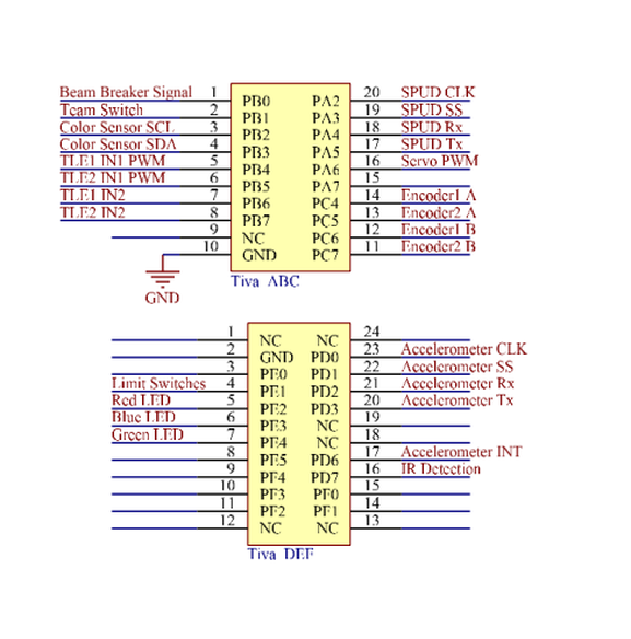
Tiva Pinouts
All the Tiva pinouts labeled with each sensors used.
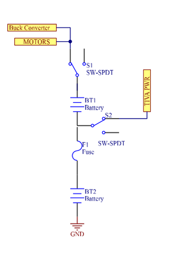
Power Distribution
Using 2 Ni-Cd batteries in series, two switches and a 5A fuse between each battery, 7.2v and 14.4v are provided to the various components of the Tractor. After the first battery which supplies 7.2V, one line is used to power the Tiva microcontroller. From the series combination of the first and second batteries, the motors and a buck converter are fed 14.4 volts. The buck converter is used to switch 14.4V to 5V for driving a servo.
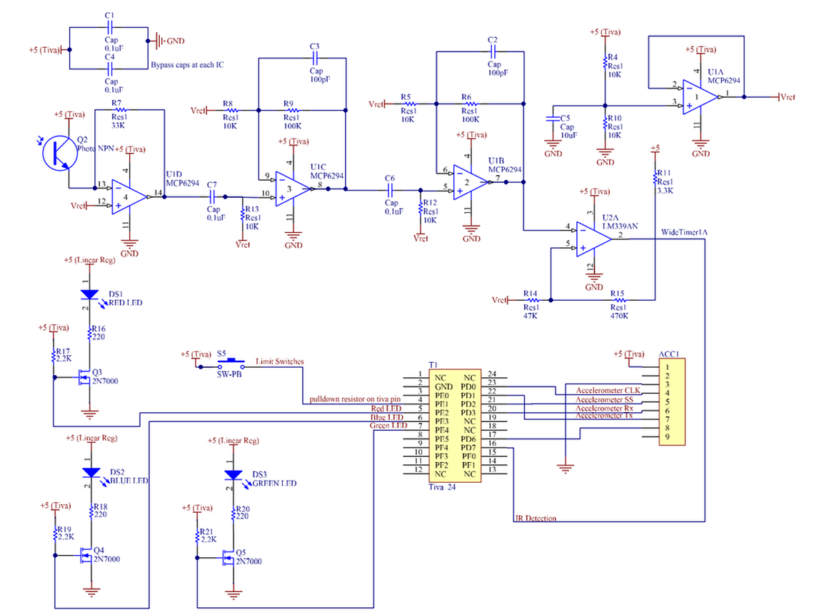
IR Detection/LEDs
3 LEDS (Blue, Red, and Green) were used to indicate which company the tractor was mining for. The team switch was used to switch between turning on the Red LED for Team CKH and turning on the Blue LED for Team GHI. A green LED was used to indicate when permits are issued (LED on) or expired (LED off).
For the IR Detection circuit, a linear photo-transistor was placed in series with two gain stages and an inverting comparator with hysteresis to detect square waves at the frequency of the IR signal emitted by the MINERs. The two gain stages provided a total gain of 100 to the input signal as the Tractor should be able to detect IR from about 8 feet away at the maximum. High pass filters were used to remove any noise and interference with ambient light through the IR phototransistor.A pull down resistor was enabled through software on port PE1 for the limit switch.
The accelerometer is connected to the Tiva by 4-wire SPI.
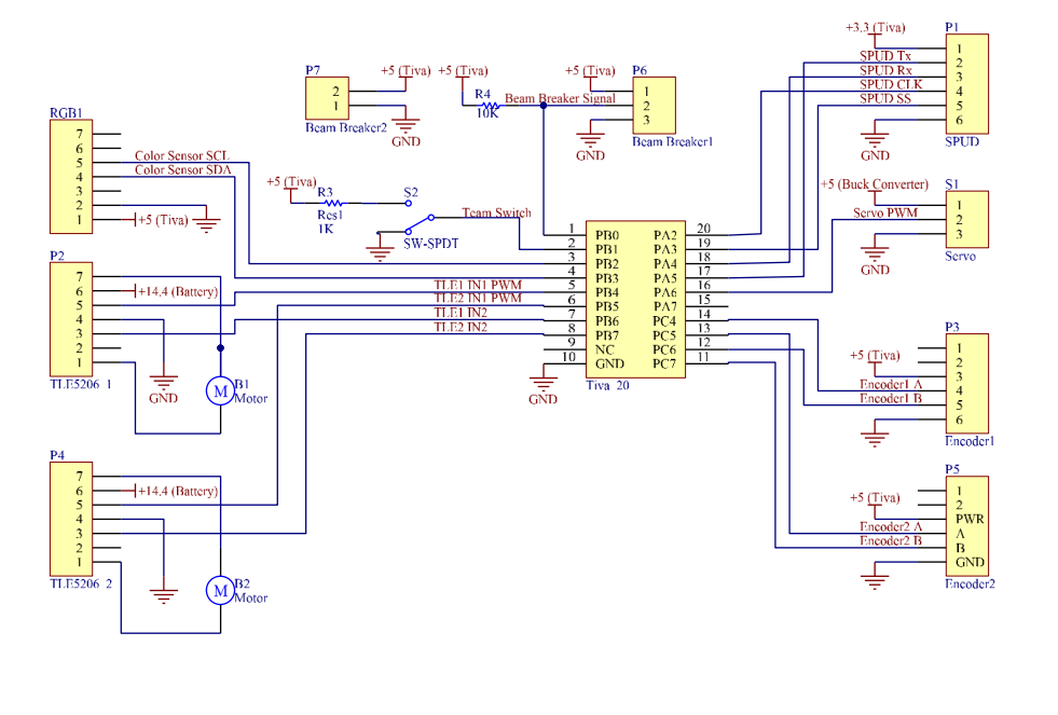
Other Sensors
Other sensors included were color sensor (RGB1), motor drivers (TLE5206), beam breaker, SPUD, servo, and encoders.
Two wires from the Tiva are connected to the Color Sensor for I2C communication.
The SPUD is connected to the Tiva by 4-wire SPI.
The Tiva connects to two inputs each of the motor drivers (TLE5206). One input is PWM and one is a digital low signal.
The encoders’ signal lines (A and B) are connected to the Tiva. An interrupt was registered every time there was a rising edge on the encoders.
The beam breaker consists of 2 parts - an IR receiver and an emitter. When a MINER is captured inside the Tractor’s U-shape, the receiver no longer gets an IR signal from the emitter and a digital low is registered on the Tiva.
Once a MINER is captured inside the Tractor and the beam breaker’s signal is broken, a servo is used to close a laser-cut piece of duron acting as a gate to hold the MINER in place.